
Demonstrating Environmental Readiness for Military and Defense Equipment
Military equipment must perform reliably in the environments where it will be transported, stored, operated, and maintained. MIL-STD-810 environmental testing provides a framework for evaluating how products respond to environmental stresses such as temperature extremes, vibration, shock, humidity, altitude, corrosion, and water exposure throughout their lifecycle. Rather than prescribing a single pass/fail test program, the standard emphasizes developing a tailored environmental qualification test plan based on the product’s intended use and operating environment. MIL-STD-810 testing is applied to military electronics, defense systems, ruggedized commercial products, UAV and drone systems, avionics, and any hardware requiring environmental durability qualification for military or aerospace procurement.
Intertek helps manufacturers develop and execute MIL-STD-810 environmental qualification programs that align with military procurement requirements, customer specifications, and real-world operating conditions. From First Article Testing (FAT) and qualification testing to environmental simulation and reliability evaluations, our engineers work with manufacturers to identify the most appropriate test methods and procedures for their products. Our ISO/IEC 17025 accredited laboratory provides MIL-STD-810 testing services including vibration testing, shock testing, temperature testing, humidity testing, altitude testing, salt fog testing, sand and dust testing, and combined environment testing for defense, aerospace, and ruggedized commercial programs.
Understanding MIL-STD-810 Compliance Requirements
One of the most common misconceptions is that a product can simply be "MIL-STD-810 certified." In reality, MIL-STD-810 is a collection of environmental test methods and engineering guidance. Compliance is typically demonstrated through a documented test plan, successful completion of applicable test methods, and supporting qualification reports.
Successful MIL-STD-810 qualification begins with understanding:
- The intended operating environment
- Transportation and storage conditions
- Expected service life
- Applicable military or customer procurement requirements
- Product performance requirements during and after testing
Because no two products experience identical environmental conditions, test programs are often customized to the specific application.
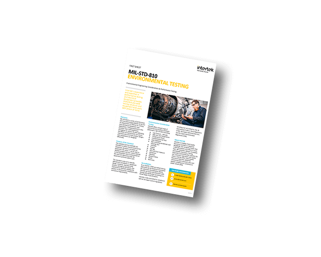
Learn more about Intertek's testing and evaluation capabilities for MIL-STD-810: Environmental Engineering Considerations & Performance Testing with our complimentary fact sheet download.
MIL-STD-810 Environmental Test Methods
Method 500.6 exposes material to low-pressure environments representative of altitudes from sea level up to 40,000 ft (12,192 m) or higher for air transport scenarios, with chamber pressure reduced to approximate ambient pressure at the test altitude per the U.S. Standard Atmosphere. Three procedures are defined: Procedure I (storage) verifies structural integrity and seal performance under prolonged low-pressure soak; Procedure II (operation) evaluates functional performance including cooling efficiency, dielectric strength, and arc-over voltage margins in electrical systems; and Procedure III (rapid decompression) simulates pressure loss events in cargo aircraft, typically executing a pressure altitude step change from 8,000 ft to 40,000 ft in two minutes or less. Critical failure modes include corona discharge and dielectric breakdown in high-voltage circuits due to reduced air density (outgassing of trapped solvents or adhesives, lubricant vaporization, and seal extrusion or blowout from differential pressure across enclosure walls. Temperature control during testing must account for adiabatic cooling during rapid decompression, which can produce condensation or frost on and within the test item independent of the chamber set point. Altitude testing and low-pressure qualification per MIL-STD-810H Method 500.6 is required for any defense product transported by air, deployed at elevation, or installed in unpressurized aircraft bays or airborne platforms.
Method 501.7 addresses material exposure to elevated temperatures from two physically distinct sources: diurnal natural thermal cycling driven by solar loading and ambient temperature variation, and induced temperature conditions from confined storage or platform-generated heat. Procedure I (storage) uses a constant high-temperature soak, typically +71 degrees C for hot-dry or +49 degrees C at 95% RH for warm-humid, to assess dimensional stability, lubricant migration, and mechanical property retention of polymers and adhesives. Procedure II (operation) requires the material to function within specification at elevated temperature after thermal stabilization, verified by monitoring internal component temperatures until the rate of change is less than 2 degrees C per hour. Procedure III (tactical-standby to operational) evaluates the transition from a cold-soaked storage state to operational temperature, relevant for equipment that must function immediately after being moved from a cold storage environment to a hot operational one. Failure mechanisms include softening and creep of thermoplastic components, de-rating or parametric drift in semiconductors and capacitors (particularly electrolytic types), lubricant thinning leading to bearing failure, and outgassing of potting compounds that contaminate optical or sensor surfaces. High temperature testing per MIL-STD-810H Method 501.7 is a core requirement for military electronics qualification, battery system qualification, and defense hardware intended for hot-dry or warm-humid operational environments including desert and tropical climates.
Method 502.7 evaluates material at cold temperatures ranging from -20 degrees C for basic ground equipment to -65 degrees C for high-altitude airborne systems, with test temperature selection driven by the lowest expected operational or storage temperature from the Life Cycle Environmental Profile. Procedure I (storage) soaks the non-operating material to thermal equilibrium at the minimum temperature, then checks for physical damage such as cracked seals, fractured solder joints, and delaminated laminates before and after warming. Procedure II (operation) requires the material to function within specification while cold-soaked, targeting failure modes including increased dynamic viscosity of lubricants preventing mechanical actuation, embrittlement of polymeric seals below their glass transition temperature, reduced electrochemical output of batteries, and increased on-resistance of MOSFETs and threshold shifts in linear ICs. Procedure III (manipulation) assesses the ability of operators to handle controls, fasteners, and connectors while wearing cold-weather gloves, an ergonomic and human factors consideration beyond purely material performance. Thermal stabilization criteria require monitoring material internal temperature to confirm equilibrium prior to initiating functional evaluation, typically defined as less than 2 degrees C change per 30-minute interval. Low temperature testing per MIL-STD-810H Method 502.7 is a standard qualification requirement for ground vehicle electronics, airborne systems, battery packs, and military equipment deployed in arctic, cold-weather, or high-altitude environments.
Method 503.6 subjects material to rapid temperature transitions between hot and cold extremes, with transfer times of one minute or less between chambers to induce thermally driven mechanical stress from differential coefficients of thermal expansion (CTE) between dissimilar materials. Procedure I (operating) requires the material to be powered on during shock cycles and monitors for functional failures during the transition, capturing failures that would not manifest during slow thermal ramp testing; Procedure II (non-operating) focuses on structural integrity after multiple cycles. Default test temperatures are typically selected from the combination of Method 501 high temperature and Method 502 low temperature extremes for the material category, with the number of cycles (minimum three, often 20 or more for qualification) based on anticipated life cycle exposure. Primary failure modes include fracture of soldered interconnects in surface mount assemblies from CTE mismatch between component bodies and PCB substrates (particularly ceramic capacitors and BGAs), delamination of bonded assemblies, cracking of conformal coatings, and failure of glass-to-metal hermetic seals. The rate of temperature change in single-chamber ramp testing (Procedure II alternative) must be validated to produce thermal gradients within the test item equivalent to those generated by chamber-transfer methods. Temperature shock testing per MIL-STD-810H Method 503.6 is a standard thermal cycling qualification test for defense electronics, avionics assemblies, and military hardware subjected to rapid transitions between operational and storage thermal environments.
Method 504.3 characterizes the effects of immersion in, spray exposure to, or contact with operational fluids on material structural materials, protective finishes, and sealing systems, recognizing that many failure modes arise from fluid contact rather than environmental extremes alone. Test fluids are organized into groups including petroleum fuels (JP-8, Jet A, diesel), hydraulic fluids (MIL-PRF-5606, MIL-PRF-83282), lubricants, deicing and anti-icing fluids (MIL-A-8243), cleaning agents, battery electrolytes, and human physiological fluids where relevant to the operational scenario. Exposure methods include complete immersion for specified durations, intermittent spray application, and wicking contact through wicks or absorbent materials to simulate fluid infiltration through seal gaps. Failure criteria are material-specific and include percent change in tensile strength, elongation at break, or Shore hardness for elastomers; coating adhesion loss per ASTM D3359; swelling or softening of thermoplastic housings; and electrical insulation resistance degradation below specified minimums. The standard requires that fluid exposure scenarios be traceable to documented operational and logistics support activities, and fluid selection should account for fluid mixing that occurs in realistic field conditions.
Method 505.6 uses controlled solar simulation to evaluate two distinct degradation mechanisms: thermal loading from absorbed solar irradiance, and photodegradation (actinic effects) from ultraviolet spectral components between 280 nm and 400 nm. Procedure I (thermal effects) uses a solar spectrum lamp calibrated to 1,120 W/m2 at the material surface to establish equilibrium surface temperatures representative of worst-case geographic solar loading, targeting hot-dry climatic category conditions where black-body surface temperatures can exceed +85 degrees C even with moderate ambient air temperature. Procedure II (actinic effects) extends UV exposure over a minimum 10-day cycle to evaluate photodegradation of polymers, organic coatings, adhesives, rubber compounds, and sealants, with failure manifested as surface chalking, cracking, color shift beyond acceptance limits, or loss of mechanical properties. Critical design considerations include UV stabilizer depletion in outdoor-rated polymers, discoloration of optical windows or filters from UV darkening of glass or fluoropolymer materials, and embrittlement of cable jackets and gasket materials. The test requires documentation of the material's operational geographic area to select the appropriate solar radiation level, as values vary significantly between desert, tropical, and temperate climatic categories.
Method 506.6 evaluates sealing integrity and material degradation from rainfall exposure using two primary procedures: Procedure I (rain and blowing rain) uses a nozzle array producing rainfall rates from 1.7 mm/hr to 40 mm/hr with optional wind-driven rain at horizontal velocities up to 18 m/s, and Procedure III (drip) simulates rain water that has collected on overhead structure dripping onto the material during storage or transport. Rain impaction energy at the higher test rainfall rates is sufficient to erode soft coatings, damage exposed connector contacts, and drive water past lip seals not designed for positive water pressure. The method distinguishes between splash and drip exposure (static head pressure) and blowing rain (dynamic stagnation pressure), as each places qualitatively different demands on seal geometry and retention force. Test configuration must represent the worst-case operational orientation of the material relative to the rain source, including any inverted or side-mounted positions encountered during transport. Post-exposure evaluation requires inspection for water ingress into sealed enclosures, measurement of insulation resistance between circuit conductors if applicable, and functional check of all material operating modes. Rain and blowing rain testing per MIL-STD-810H Method 506.6 is required for outdoor-deployed military equipment, vehicle-mounted systems, aircraft external stores, and any defense product with enclosure sealing requirements for field use.
Method 507.6 evaluates material resistance to high-humidity environments through two procedures: Procedure I (aggravated) exposes material to 95% RH at +40 degrees C for a minimum of 10 days, targeting rapid identification of corrosion susceptibility and moisture ingress; Procedure II (cyclic) uses a 24-hour temperature-humidity profile that drives condensation on and within the material by cycling from a cold soak (as low as +25 degrees C) to high temperature and humidity, replicating diurnal conditions in tropical environments. Condensation cycle testing is more discriminating than constant humidity because the temperature drop causes moisture in humid air entrapped within the enclosure to condense on internal surfaces, including circuit boards, connector contacts, and optical elements. Galvanic corrosion rates are strongly accelerated by the electrolyte film formed during condensation, particularly at dissimilar metal interfaces common in aluminum housings with steel fasteners. Failure modes include dendrite growth causing shorts on high-impedance circuit nodes, connector contact corrosion increasing contact resistance beyond specification limits, swelling of hygroscopic materials (certain nylons, fiber composites) causing dimensional tolerance exceedances, and degradation of conformal coating adhesion. The method also considers biological growth initiation as a precursor to Method 508 fungus testing. Humidity testing per MIL-STD-810H Method 507.6 is a standard environmental durability requirement for military electronics qualification, tactical communications equipment, avionics, and ruggedized systems deployed in tropical or maritime climates.
Method 508.8 determines whether material materials provide nutrient substrates that support fungal proliferation, with failure defined as fungal growth on or within functional surfaces that impairs performance or accelerates material degradation. The test inoculates exposed material surfaces with a suspension of at least five fungal species including Aspergillus niger, Aspergillus flavus, Penicillium funiculosum, Chaetomium globosum, and Trichoderma viride at a minimum concentration of 1x10^6 spores per milliliter, incubating at +30 degrees C plus or minus 1 degree C and greater than 90% RH for 28 days. Fungi metabolize organic materials including cellulose-based insulation, natural rubber, organic coatings, lubricants, and certain plasticizers in PVC cable jackets, producing organic acids that attack adjacent metals and create conductive pathways on otherwise insulating surfaces. The standard allows a material assessment prior to biological testing: if all exposed surfaces are confirmed to be constructed entirely of non-nutrient materials, a documented engineering judgment may be substituted for the biological test. Post-test inspection grades growth using a 0-4 scale per ASTM G21, and material showing growth at Grade 2 or higher on functional surfaces is considered a test failure requiring redesign or coating change.
Method 509.6 exposes material to a continuous 5% sodium chloride fog at pH 6.5-7.2 and +35 degrees C for durations typically ranging from 48 to 500 hours, generating an accelerated corrosive environment intended to assess coating integrity and base material corrosion resistance rather than to directly simulate specific field environments. Salt spray testing per MIL-STD-810H Method 509.6 is a standard corrosion qualification test for military electronics, ground vehicle components, naval equipment, and defense hardware with documented coastal or marine operational exposure. The salt fog environment is significantly more corrosive than natural marine atmospheres due to the continuous surface wetness maintained by fog deposition, which eliminates the drying periods that occur in real coastal environments and that allow protective passivation layers to stabilize. Primary assessment criteria include blistering, rusting, or adhesion loss of organic coatings per ASTM D714 and D3359, galvanic corrosion at interfaces between dissimilar metals, white corrosion of zinc or cadmium platings, pitting of anodized aluminum, and contact resistance degradation at unplugged electrical connectors. The test is most useful as a comparative tool for ranking coating systems or finish specifications and does not directly predict field service life without correlation data from known materials. Threaded fasteners, hermetic connectors, and hinged or sliding mechanical interfaces are particularly vulnerable and should be individually evaluated after exposure.
Method 510.7 addresses two distinct particle size regimes with separate procedures: Procedure I (blowing dust) uses particles predominantly below 150 micrometers at concentrations of 0.18 to 1.06 g/m3 and wind velocities of 1.5 to 8.9 m/s to evaluate filtration bypass, seal ingress, and abrasion of soft surfaces; Procedure II (blowing sand) uses particles from 150 to 850 micrometers at velocities up to 18 m/s (32.8 m/s for some applications) to evaluate impact erosion, abrasion of optical coatings and transparent covers, and mechanical jamming of exposed mechanisms. Dust particles at the fine end of the spectrum are most penetrating, capable of passing through labyrinth seals and filter media that would stop larger particles, and accumulate within enclosures on circuit boards, potentiometers, and relay contacts. Sand particles at high velocity generate impact pressures sufficient to pit anodized aluminum, erode thermal spray coatings, fracture anti-reflection coatings on optical windows, and score bearing races in exposed rotating assemblies. Test chamber designs must maintain uniform particle concentration and velocity across the test item, verified with isokinetic sampling probes at the test item location. Post-test disassembly and inspection of critical interfaces including gear meshes, bearing races, filter media, and sealed connectors are required to characterize ingress depth. Sand and dust testing per MIL-STD-810H Method 510.7 is a required environmental durability qualification test for military electronics, ground vehicle systems, small arms accessories, and defense equipment with documented operational exposure to desert, arid, or high-particulate environments.
Method 511.6 verifies that material operating in a fuel-air explosive atmosphere does not provide an ignition source sufficient to initiate combustion, using a test mixture at or near the stoichiometric concentration that maximizes ignitability, typically 3.5% by volume ethylene or 4.1% hexane in air per applicable procedure. The material is operated through its full duty cycle including all switching events, motor starts, and relay operations within the explosive chamber, since the brief arc energy of a single switching contact closure can be sufficient to ignite a sensitive mixture even when steady-state electrical characteristics appear benign. Test facility requirements include remotely operated fill and purge systems, pressure monitoring to detect deflagration events, reinforced chamber construction rated for internal overpressure, personnel exclusion during test, and validated gas mixing and concentration measurement equipment. A single confirmed ignition event is an unconditional test failure with no opportunity for partial credit; redesign must address the specific ignition mechanism identified, which may require arc suppression circuits, hermetic sealing of all switching elements, purge-and-pressurize enclosure design, or intrinsically safe circuit topologies. The method covers the complete material including any internal pyrotechnic devices or energy storage elements and does not exempt components that may be individually rated for use in hazardous locations if system-level integration introduces additional ignition risks.
Method 512.6 evaluates enclosure sealing performance under hydrostatic pressure conditions produced by submersion, using two procedures that address distinct operational scenarios: Procedure I (immersion) submerges the material to 1 m water depth (9.8 kPa gauge pressure at the enclosure surface) for 30 minutes, and Procedure II (fording) addresses vehicle or equipment crossing water obstacles at shallower depth with potential for wave wash. Hydrostatic pressure loading on enclosure seals differs fundamentally from spray or condensation exposure because it applies a sustained pressure differential across every seal face, extrusion groove, and cable entry, driving water through any path that provides a pressure drop below the test head. IP Code correlations are informative but not directly equivalent: IPX7 per IEC 60529 (1 m for 30 min) nominally aligns with Procedure I parameters, but the standard allows different test conditions where the operational scenario requires deeper submersion or longer duration. Failure detection requires measurement of insulation resistance between circuit conductors both before and after immersion, gravimetric measurement of water intrusion volume in sealed enclosures with absorbent material inside, and functional check of all operating modes. Internal pressure equalization ports with hydrophobic membranes, which are commonly used to mitigate breathing-induced moisture ingress, must be evaluated for bypass under sustained hydrostatic head.
Method 513.8 uses a centrifuge to apply sustained linear acceleration at levels and in axes representative of flight maneuver loads, rocket motor burn acceleration, or other sustained g-environments, with the test item mounted at a radius from the centrifuge center axis chosen to produce the required centripetal acceleration at the material center of mass. Applicable acceleration levels range from approximately 1.5 g for artillery shell setback to 20 g or more for rocket-boosted munitions, with the operational axis of acceleration defined by the Life Cycle Environmental Profile analysis and platform dynamics data. Failure modes under sustained acceleration include permanent deformation of cantilevered structures loaded perpendicular to their primary load axis, relay contact force reversal leading to contact chatter or false actuation, displacement of potted components within their encapsulant under sustained load, and bearing preload loss in precision gimbal assemblies. The standard requires measurement of centrifuge acceleration level and duration using a calibrated accelerometer mounted at the test item center of mass, and functional monitoring during acceleration where the material is required to operate under load. Gyroscopic effects from the centrifuge rotation must be accounted for in axis alignment, particularly for assemblies containing spinning mass elements such as reaction wheels or gyroscopes.
Method 514.8 is the most widely applied method in MIL-STD-810H and is the foundation of most random vibration qualification testing and vibration qualification programs for military electronics, defense systems, and aerospace equipment. It covers laboratory simulation of the vibration environments material experiences throughout its service life across ground transport, aircraft carriage, rotary wing, and on-equipment operational vibration sources. The standard defines a hierarchy of data quality: field-measured data from the specific platform and configuration is preferred, followed by data from similar platforms with documented correlation, followed by generalized default spectra provided in the method appendices; use of default spectra without a documented rationale for why measured data is unavailable is discouraged. Procedure I (general vibration) uses broadband random vibration with power spectral density (PSD) profiles defined in g2/Hz, applied sequentially in three orthogonal axes for durations derived from test severity analysis to accumulate equivalent fatigue damage; Procedure II (loose cargo) applies higher-level random vibration representing unpackaged material in truck transport; Procedure III (assembled aircraft stores) applies combined random and swept sine vibration representing carriage on aircraft pylons. Vibration fatigue life equivalencing using Miner’s rule with the Basquin fatigue exponent (typically b = 6.4 for electronics per MIL-HDBK-217 derived models) translates real-world vibration duration to equivalent laboratory test duration at elevated test levels, commonly accepting test factors of 3x to 10x duration compression with appropriate PSD level adjustment. Monitored failure modes include solder joint fatigue in surface mount assemblies, potentiometer and variable resistor wear, fastener and insert pull-out, wire harness chafing at clamp points, and resonant fatigue of sheet metal brackets, with resonance dwell testing sometimes added to accelerate identification of critical modes. Electrodynamic shaker testing per MIL-STD-810H Method 514.8 is required for virtually all defense electronics qualification programs, UAV payload qualification, and ruggedized electronics destined for ground vehicle, rotary wing, or fixed-wing carriage environments.
Method 515.8 simulates high-intensity acoustic noise environments generated by jet and rocket propulsion, using either a progressive wave tube (PWT) for directional acoustic loading or a reverberation chamber for diffuse field exposure, with overall sound pressure levels (OASPL) typically ranging from 130 dB to 165 dB re 20 microPa for aerospace applications. The acoustic spectrum is specified as a one-third octave band SPL profile across the frequency range of 31.5 Hz to 10,000 Hz, with the profile shape determined from measured data at the material mounting location on the host platform; rocket vehicle base environments and jet exhaust fields produce peak energy in the 100-500 Hz range while gun blast environments have dominant energy at lower frequencies determined by breech volume and barrel geometry. Acoustic loading excites structural panels in flexural vibration with amplitudes proportional to the panel acoustic radiation resistance, producing spatially distributed random vibration loading that is fundamentally different from point-force excitation on a shaker and cannot be replicated by single-axis shaker testing alone. Critical failure mechanisms include high-cycle acoustic fatigue of thin aluminum skins, honeycomb face sheet disbond from repeated strain cycling, circuit card component failure from vibro-acoustic excitation of the PCB first bending mode, and failure of crimped wire terminations from strand fatigue at the termination barrel. The method requires that the test item be operated through all functional modes during exposure, since internal resonances of active components such as relay armatures and crystal oscillators may cause functional failures at lower SPL than structural failures.
Method 516.8 is the primary MIL-STD-810H method for shock testing and mechanical shock qualification, addressing shock loads from handling, transport, and operational events through six procedures: Procedure I (functional shock) applies three classical pulses (half-sine, sawtooth, or trapezoidal) per axis per direction on a shock machine at levels typically from 20 g to 40 g with durations of 6 to 11 ms; Procedure II (transit drop) simulates packaged or unpackaged drops from 0.3 m to 1.2 m heights depending on material mass; Procedure III (fragility) determines the critical velocity change (delta-V) and peak acceleration that causes failure, used to establish cushioning requirements; Procedure IV (bench handling) simulates drops and impacts during maintenance; Procedure V (crash hazard) applies high-level shocks representing structural survival requirements during vehicle crash events; and Procedure VI (catapult/arrested landing) is specific to carrier-based naval aircraft, applying velocity-change pulses up to 10 m/s simulating catapult launch and arresting gear deceleration. Shock response spectrum (SRS) analysis at a damping ratio of Q = 10 (5% critical damping) is the standard characterization tool, defining the peak acceleration response of a single-degree-of-freedom oscillator as a function of natural frequency across the frequency range of interest; test pulse parameters are selected to match the SRS of the field shock environment at the material mounting location. Failure modes include solder joint fracture from peak g-overload, relay contact bounce causing false state transitions, brittle fracture of ceramic capacitors and crystals, permanent deformation of structural members loaded beyond yield, and loss of engagement in detent mechanisms. MIL-STD-810H shock testing services including transit drop testing, half-sine pulse shock, and SRS-based qualification are required for defense electronics, avionics, tactical communications equipment, and shipboard systems.
Method 517.2 addresses the shock environment produced by pyrotechnic devices including linear shaped charges, explosive bolts, pin pullers, and separation nuts, which generate stress waves with frequency content predominantly above 1,000 Hz and peak accelerations that can exceed 10,000 g locally, making classical shock machine replication impractical and SRS synthesis on a standard shaker system bandwidth-limited. Three simulation approaches are defined in order of fidelity: the preferred method uses actual or equivalent pyrotechnic devices on a structurally representative test fixture to replicate the source mechanism; mechanical impact simulators use projectile or pendulum impact on resonant fixtures tuned to match the target SRS; and electrodynamic shaker synthesis uses SRS-matched random transient waveforms, accepted only when the test frequency range is within the shaker bandwidth and the required SRS amplitude is achievable without exceeding shaker force limits. Pyroshock SRS measurement and characterization requires accelerometers with high shock survival ratings (typically greater than 10,000 g), very low mass to avoid fixture loading, and data acquisition systems with sampling rates of at least 100 kHz to resolve the high-frequency content without aliasing. Failure mechanisms unique to pyroshock include fracture of ceramic capacitor bodies from high-frequency stress wave transmission through PCBs, relay contact separation from armature inertia response to high-frequency loading, and fracture of wire bond interconnects in microelectronic devices from die attach stress wave reflections. Measurement uncertainty in pyroshock SRS characterization is larger than for other shock methods and must be accounted for in test tolerance and pass/fail determination.
Method 518.2 exposes material to controlled concentrations of sulfur dioxide (SO2) at 75 parts per million by volume combined with 95% relative humidity at +40 degrees C, creating a sulfurous acid (H2SO3) surface film that aggressively attacks metallic and organic surface finishes in a manner representative of industrial pollution and acid rain environments. The test duration of 24 hours at these conditions is intended to represent an accelerated equivalent of long-term industrial atmosphere exposure, with the acceleration factor referenced to natural atmospheric SO2 concentrations typically on the order of 0.1 ppm in polluted urban environments. Primary corrosion mechanisms include attacks of zinc and cadmium platings forming zinc or cadmium sulfate salts, tarnishing of silver and copper electrical contacts reducing contact conductivity, and hydrolytic degradation of polyurethane and alkyd coatings accelerated by the acidic surface environment. The method is applied selectively to material with documented operational exposure to industrial atmospheres, volcanic regions, or areas with known acid rain conditions, and is often combined with salt fog testing to represent combined marine-industrial environments. Post-test evaluation criteria include corrosion rating of metallic surfaces per ASTM B537, adhesion testing of organic coatings, and measurement of electrical contact resistance for exposed connector interfaces.
Method 519.8 addresses the structurally transmitted vibration generated by firing of aircraft or vehicle-mounted automatic weapons, which produces a periodic random vibration environment with energy concentrated at the weapon firing frequency and its harmonics superimposed on a broadband random floor, requiring a combined deterministic-plus-random test approach distinct from standard Method 514 broadband random testing. Firing rates for typical aircraft guns range from 1,500 to 6,000 rounds per minute (25 to 100 Hz), placing harmonic energy within the structural vibration frequency range most damaging to electronic assemblies, with the periodic component amplitude potentially exceeding the broadband random component by 10 to 20 dB at resonant frequencies of the airframe structure. The standard defines three test methods based on available data quality: Method A uses directly measured field data to drive the shaker in time waveform replication; Method B defines the test spectrum as a combination of narrowband spectral lines at firing harmonics superimposed on a broadband PSD; and Method C uses a simplified broadband PSD that envelops the combined spectrum without resolving the harmonic structure. Fatigue equivalencing from burst firing sequences to continuous test duration requires characterization of the duty cycle, including burst length, inter-burst interval, and total number of rounds per sortie, to compute equivalent damage-weighted exposure time at test conditions. Material susceptibility to the periodic component is not well-predicted by standard broadband random testing because the periodic loading drives deterministic resonances at predictable frequencies rather than exciting all modes stochastically.
Method 520.4 applies simultaneous combinations of temperature, humidity, reduced pressure, and mechanical vibration to expose synergistic failure mechanisms that do not manifest in sequential single-stressor testing, recognizing that the physical interaction of environmental stressors can produce material response fundamentally different from superposition of independent exposures. The combined environment is particularly relevant to avionics in unpressurized bays, wing-mounted stores, and externally mounted sensors that experience altitude-driven pressure reduction concurrent with vibration from the airframe and thermal and humidity variation across the flight profile. Reduced air pressure modifies heat transfer coefficients from both convection and forced air cooling, increasing junction temperatures in powered electronics beyond those measured at sea level for the same ambient temperature, a coupling effect that is not captured when altitude and temperature are tested independently. The simultaneous application of humidity and vibration accelerates fretting corrosion at contact interfaces, since the mechanical micro-motion from vibration continuously disrupts passivation oxide layers on contact surfaces while the humid atmosphere drives re-oxidation of the exposed metal between cycles. Test facility requirements include a chamber capable of achieving the required pressure reduction while maintaining vibration excitation (typically using a servo-hydraulic shaker rather than electrodynamic to permit low-pressure chamber access), and the test sequence must define thermal ramp rates, vibration spectral content, and altitude profile as time-synchronized schedules.
Method 521.4 simulates ice accretion on material surfaces from freezing rain and freezing drizzle using a spray system producing controlled water droplet size distributions at below-freezing chamber temperatures, building ice layers of defined thickness and radial extent on protruding features before requiring the material to demonstrate operability or structural integrity. Two procedures are defined: Procedure I (icing) uses supercooled water droplets representative of in-cloud icing conditions at liquid water content values of 0.2 to 3.0 g/m3 and mean volumetric droplet diameters of 15 to 40 micrometers, consistent with FAR Part 25 Appendix C continuous maximum icing envelopes; Procedure II (freezing rain and freezing drizzle) uses larger droplets at lower liquid water content representative of precipitation icing. Ice accretion on antenna elements modifies electromagnetic aperture and impedance matching, on pitot-static probes obstructs pressure sensing orifices, and on control surface gaps or hinge lines prevents mechanical actuation beyond the breakout force available from actuators. Radome materials must maintain RF transmission performance with ice loading, since ice has a dielectric constant of approximately 3.2 compared to 1.0 for air, shifting antenna beam patterns and insertion loss. Post-icing functional verification must be conducted without artificial ice removal to confirm the material can operate in the iced condition, not merely that it survives icing when subsequently cleared.
Method 522.2 addresses the structurally transmitted shock environment in armored vehicles from non-penetrating ballistic impact, where kinetic energy from a projectile striking the vehicle hull generates stress waves that propagate through the structure and produce high peak accelerations at interior mounting locations without hull breach. Measured ballistic shock environments in armored fighting vehicles from relevant threat projectile impacts produce SRS values ranging from 1,000 g to over 10,000 g in the 100-10,000 Hz frequency range at crew station and equipment mounting locations, with the specific SRS shape and amplitude depending on projectile mass and velocity, armor material and geometry, and structural transmission path between impact and measurement location. Laboratory simulation is accomplished using large-mass drop (Hopkinson bar or drop weight) fixtures or gas-gun impactors on welded steel simulation fixtures representative of the armored vehicle structure, with the fixture natural frequency tuned to produce the required SRS without exceeding the material's structural limits in non-target modes. Post-test functional verification must include all operating modes since ballistic shock produces broadband excitation sufficient to drive multiple structural resonances simultaneously, and failure modes including relay false actuation, connector separation, and cracked ceramic components may occur without visible structural damage to the material outer housing. Correlation between laboratory simulation SRS and field measurement SRS is required documentation for test adequacy.
Method 523.5 is a combined-environment method for aerospace structures and equipment requiring simultaneous application of high-intensity acoustic noise, structural vibration, and elevated or reduced temperature, targeting the failure modes driven by the interactive thermal and mechanical loading during launch vehicle ascent, supersonic flight, or high-performance aircraft maneuver regimes. The method is specifically applicable when acoustic-induced panel vibration under aerodynamic loading occurs simultaneously with aerodynamic heating or solar/exhaust thermal inputs, since material fatigue properties are temperature-dependent and the effective fatigue life reduction from thermal softening cannot be conservatively approximated by independent sequential testing at temperature and acoustic load separately. Thermoacoustic fatigue of titanium and aluminum panels in supersonic aircraft is the primary design driver motivating this method, since the simultaneous kinetic heating from Mach number-dependent stagnation temperature and the acoustic loading from turbulent boundary layer and jet exhaust produce coupled failure at panel skin gauges significantly lower than would be predicted from temperature or acoustic loading alone. Test facilities combining reverberation chambers with controlled temperature environments and supplemental mechanical vibration excitation are limited in number, requiring early program planning for access. Data requirements include measured or analytically derived acoustic SPL spectra, temperature history at the material surface, and mechanical vibration PSD at mounting interfaces, with all three environments defined as time-correlated profiles representing the critical mission phase.
Method 524 applies repeated freeze/thaw cycles to material to evaluate degradation mechanisms distinct from constant cold storage or rapid temperature shock, specifically targeting damage from ice formation within crevices, porous materials, and interfacial gaps where water has infiltrated during prior precipitation or condensation exposure. The test procedure pre-wets the material by water immersion or rain exposure per Method 506, then subjects it to freeze cycles at temperatures between -10 degrees C and -46 degrees C (with -10 degrees C representing the most aggressive condition for ice expansion pressure in confined geometry) followed by thaw cycles at room temperature or above, with the number of cycles (minimum 10) selected to represent the seasonal temperature variation cycle count over the material service life. Ice formation in crevices and between bonded surfaces generates hydrostatic pressures up to 207 MPa at temperatures below -22 degrees C per the phase diagram of water, sufficient to fracture metal castings, propagate fatigue cracks from machined stress risers, and delaminate adhesively bonded joints that withstand equivalent static tensile loads without ice presence. Coatings that pass Method 509 salt fog and Method 507 humidity testing may fail freeze/thaw when entrapped moisture beneath disbonded coating areas freezes and mechanically lifts the coating from the substrate. Post-test inspection criteria include coating adhesion per ASTM D3359, dimensional measurement of sealing surfaces for distortion, and leak testing of sealed enclosures to detect freeze-induced seal damage.
Method 525 replicates field-measured mechanical environments directly in the time domain by driving a shaker system with the measured acceleration time history processed through the inverse frequency response function of the shaker-fixture-test item system, preserving amplitude modulation, phase relationships, and transient content that are lost when the time history is reduced to a power spectral density. The drive signal computation requires a frequency response function (FRF) measurement of the shaker-fixture assembly, with the inverse FRF applied to the target time history to generate the compensated drive signal; iterative correction using the measured response error between target and achieved waveforms is typically required over multiple trial runs to achieve the waveform replication tolerances specified in the method. Acceptance criteria require that the achieved test item response waveform match the target waveform in peak amplitude within +3 dB/-6 dB and that the cumulative amplitude probability density function (APDF) match within specified bounds across the full amplitude range, ensuring that both the large-amplitude peak content and the lower-amplitude fatigue-driving content are correctly reproduced. This method is preferred when the field environment contains significant non-stationary content such as engine run-up sweeps, transient events from rough road inputs, or combined periodic-plus-random content from weapons fire, since PSD-based random vibration testing cannot replicate these time-domain characteristics. The primary limitation is that Method 525 requires high-quality measured data from the actual platform and operational scenario, and cannot be executed from default or generic environmental data; field data quality requirements including measurement bandwidth, dynamic range, and sample rate are specified in the method.
Method 526 simulates the velocity change shock input imposed on rail freight shipments during classification yard humping and switching operations, where cars are pushed over a hump and roll into stationary cars at controlled coupling speeds producing velocity changes of 1.5 to 4.9 m/s (depending on car weight and coupling speed) at the car floor level over pulse durations of 150 to 600 ms. The long-duration, moderate peak acceleration character of rail coupling shock distinguishes it from Method 516 transit drop shock, which produces higher peak accelerations over shorter durations; rail impact primarily stresses mounting systems through large displacement strokes rather than high instantaneous inertial loading, making it more damaging to soft-mounted equipment where resonant amplification during the long pulse can produce displacement-limited failures. Test simulation uses a rail impact simulator consisting of a tracked car or sled impacted by a controlled mass drop or spring-loaded impactor, calibrated to produce the target velocity change and pulse shape verified by integrated accelerometer measurement at the test item mounting surface. Material in transit packaging must be evaluated in the fully packaged configuration representative of actual shipping, with the cushioning material installed and the container sealed, since the cushioning system response under the long-duration rail pulse determines the shock transmitted to the equipment. Failure modes specific to rail impact include displacement-limited failures of hard-mounted equipment against housing stops or adjacent structure, cumulative fastener loosening from repeated impacts, and fatigue of mounting bracket welds from the multiple impacts experienced during a typical rail transit.
Method 527 addresses vibration testing of large, spatially extended structures using two or more independently controlled exciters applied at different spatial locations, enabling replication of the cross-spectral density (CSD) matrix of the field vibration environment including both the auto spectral content at each control point and the coherence and phase relationships between excitation locations. Single-point shaker testing of structures with multiple widely spaced mounting interfaces forces the test item into vibration modes driven by a single-axis input, producing stress distributions that differ fundamentally from the distributed loading imposed by the actual operational environment where multiple excitation sources act simultaneously with defined spatial correlation. The control strategy requires either independent (uncorrelated) control of each exciter to a defined input PSD at each drive point (appropriate when field measurements show low coherence between mounting locations) or correlated multi-input multi-output (MIMO) control using the full CSD matrix, which requires the controller to synthesize drive signals that produce the specified cross-spectral relationships between control channels. Drive signal computation in MIMO control involves matrix inversion of the frequency response function matrix relating all drive points to all control points, requiring a well-conditioned FRF matrix achieved through spatial diversity of exciter locations; ill-conditioning at specific frequencies indicates insufficient spatial separation of exciters or modal overlap in the test item. The method is essential for large aerospace panels, naval hull structures, and vehicle chassis where field-measured vibration shows significant coherence between spatially separated points, indicating that simultaneous correlated loading drives critical structural modes not accessible with single-exciter testing.
Method 528 defines sinusoidal swept vibration requirements for equipment installed aboard naval surface ships and submarines, where the vibration environment is characterized by narrowband tonal excitation from propulsion shafting at blade passage frequency and harmonics, diesel generator sets at combustion firing frequency, and auxiliary machinery, rather than the broadband random spectra that dominate airborne and ground vehicle environments. Test levels are defined by frequency range and amplitude in g or displacement (peak) as a function of frequency, with the lower frequency range (1-15 Hz) dominated by ship motion and hull flexure and the higher frequency range (15-100 Hz and above) dominated by propulsion and auxiliary machinery harmonics; specific levels are drawn from applicable ship system specifications such as MIL-S-901 and MIL-STD-167 rather than defaulting to generic MIL-STD-810 parameters. The sinusoidal test format is technically appropriate because the shipboard vibration energy is concentrated at discrete, predictable frequencies with stable amplitude over time, unlike airborne or ground vehicle environments where the energy is distributed across a broad spectrum with amplitude modulation; broadband random testing of shipboard equipment would apply conservative excitation at frequencies where the real environment has negligible energy while potentially under-testing at critical machinery harmonics. Resonance dwell testing is a standard adjunct in which the swept sine is paused at identified material resonance frequencies to accumulate fatigue damage at the resonant condition, with dwell duration calculated from the expected service life exposure at that frequency. Ship shock testing per MIL-S-901 is a separate and complementary requirement addressing underwater explosion shock survivability and should not be confused with the steady-state vibration scope of Method 528.
Products Requiring MIL-STD-810 Environmental Testing
MIL-STD-810 testing is commonly performed on:
- Military electronics
- Tactical communications equipment
- Power distribution equipment
- Battery systems
- Ground support equipment
- Avionics systems
- Sensors and instrumentation
- Navigation equipment
- UAV and drone systems
- Ruggedized commercial electronics
- Vehicle electronics
- Defense and aerospace components
MIL-STD-810 Environmental Testing - Frequently Asked Questions (FAQs)
No. MIL-STD-810 is a test method standard and environmental engineering guideline. Compliance is demonstrated through testing and documentation rather than certification.
The current version is MIL-STD-810H with Change Notice 1. Earlier versions such as MIL-STD-810G are still referenced in some procurement documents and legacy programs.
MIL-STD-810H is the current revision of the standard and includes updates to environmental engineering guidance, test method references, and qualification practices. Many legacy procurement specifications continue to reference MIL-STD-810G, making it important to review contract requirements before developing a test plan.
Vibration testing (Method 514), shock testing (Method 516), temperature testing, humidity testing, altitude testing, and salt fog testing are among the most frequently requested environmental evaluations.
Yes. Although developed for military applications, MIL-STD-810 testing is frequently used to evaluate commercial products intended for harsh operating environments.
Why Choose Intertek for MIL-STD-810 Environmental Qualification Testing?
Intertek supports manufacturers throughout the environmental qualification process, from early test planning through final reporting. Our engineers can help identify applicable test methods, develop tailored test programs, and execute environmental qualification testing aligned with military, aerospace, and defense procurement requirements. We support MIL-STD-810 qualification programs for military electronics, ruggedized commercial products, avionics systems, ground vehicle electronics, UAV and drone payloads, tactical communications equipment, battery systems, navigation equipment, and defense sensors and instrumentation.
By combining MIL-STD-810 environmental testing, MIL-STD-461 EMC testing, electrical performance evaluations, and reliability assessments under one program, Intertek helps manufacturers streamline qualification efforts, reduce project complexity, and accelerate time to defense market readiness.
Contact our team to discuss your MIL-STD-810 test plan requirements, request a quote for environmental qualification testing services, or learn how we support ITAR-compliant testing for controlled defense programs.
Related Links
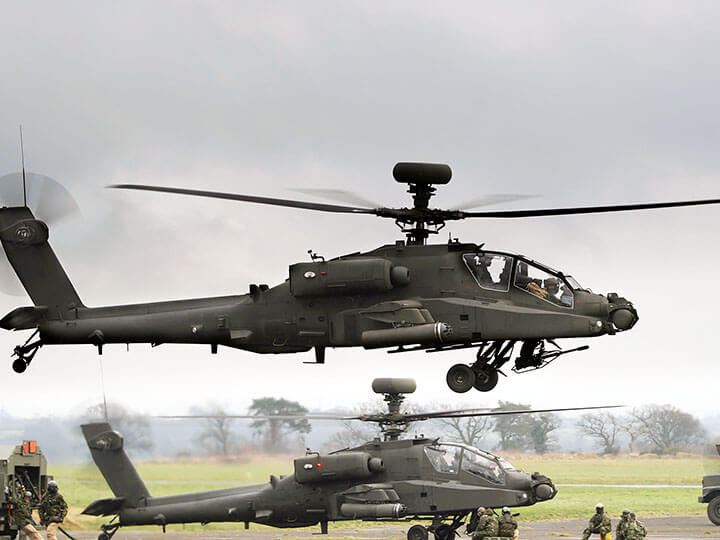
Performance Testing for Military & Aerospace (FATs, MIL-STD-810, RTCA DO-160)
From initial project stage and test plan origination to pre-compliance testing and final qualification report issuance